Radar Basics
How does Radar work
What is a Radar?
A Radar (Radio Detection And Ranging) is an instrument that can detect surrounding objects using radio waves. Thus, in the maritime world, objects such as ships, buoys or birds can be detected by Radars. The use of short-wavelength microwaves allows a very accurate measurement of the direction in which the object is detected and the distance at which it is located. In addition to the maritime domain, Radars have many other applications such as meteorology and aerial surveillance. Radars are also widely used in everyday life to measure the speed of cars on a road or the speed of a tennis ball on a court for example.
A principle similar to that of an echo

Although not using sound waves but short-wave microwaves, the principle of a Radar is the same as that of the sound. When in contact with an object, the waves reverberate and thus, the distance to the target and its direction can be accurately calculated. This information is then put in the form of visual data on a screen so it becomes readable. Let's suppose that a wave is sent to one specific direction.
The wave passes through its environment in a straight line, but when it hits an object on its path, it is reflected and part of this wave returns to its original position. This phenomenom is called reflection. It is the time it takes for this echo to return that will help to accurately determine the distance at which the object is located. Bearing to a target is determined by the direction from which a reflected echo returns. A Marine Radar scanner rotates 360 degrees about its vertical axis, using a special gear. Since we know the direction the antenna is facing when the Radar energy is transmitted, we know the bearing of targets in the path of that beam of energy. The sharper the beam, the more accurately the bearing of a target can be determined.
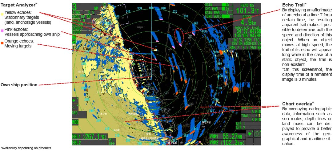
In the maritime field, the analysis of an echo makes it possible to obtain a multitude of information by calculation and logical deductions such as whether an object is moving, approaching or stationary. Signal Analyzing functions such as the "Target Analyzer" even allow these echoes to be easily distinguished by colour-codes according to their movement. Other functions such as the "Echo Trail" allow you to clearly visualize the movement of an echo.
Interpreting a marine Radar screen
How do we calculate the distance to a target?
When calculating a distance between the Radar and an object, it must be taken into account that the time (T) measured between the emission of a wave and the reception of its echo is that of the round trip of this wave since the wave is rebounded by this object. To calculate the distance (D) between the radar and an object, Time (T) needs to be divided by two.
D = 1/2 × cT
D: Distance between the Radar and the targeted object
c: Speed of light 3 × 10⁸ m/s
T: Time elapsed between first emission and reception of an echo
Since Radars use electromagnetic waves moving at the speed of light, they have the advantage of processing information very quickly.
About pulse wave
Radars emit microwaves in a pulsatile way and these waves are called square waves. The utility of pulsed waves lies in the ability to accurately determine a distance, while allowing for the reception of energy returned from radar targets in the path of the emitted wave.
Radar transmits pulsed waves repeatedly in a fixed cycle. The pulse width of a pulsed wave and its repetition frequency are determined by the distance at which the target is located. Let us consider a wave whose pulse width is 0.8 micro-seconds. If the frequency is set to 840Hz, then this 0.8 micro-second wide wave will be repeated 840 times during one second.
Directivity of the Antenna Unit
If the distance to the target can be known by measuring the time that elapses until the reflected wave is received, the direction in which the object is located can be determined with a directional antenna. Although the antennas used on ships rotate 360°, their extremely precise directivity (i.e. the accuracy angle of an antenna) allows the target to be located with very high accuracy. However, since the reverberated signals are extremely weak compared to the transmitted signal, it is necessary to amplify these signals using an amplifier so that they can be exported into visual data.
Line of sight of a Radar
Radar waves propagate along Earth's surface, but due to diffraction effect, these waves propagate in a slightly curved manner. The degree of diffraction is determined by many factors including atmosphere density. In general, the diffraction curve allows the wave to go beyond the line-of-sight by about 6%.
D ≒ 2.2(√H1 + √H2)
D: Radar line-of-sight (NM)
H1: Altitude at which the Radar is installed (m)
H2: Altitude of the object reverberating the signal (m)

For example, if we assume that the height at which the antenna is located on a boat is 16m and the altitude of the detected object is 9m, then the radar line-of-sight will be about 15 nautical miles. The range of a radar can be increased by simply installing the antenna higher and in the same way, the higher the altitude of an object, the farther it can be detected.
Structure of a Radar
- To explain the structure of a Radar, we will use the latest magnetron Radars as an example.
Radar Components
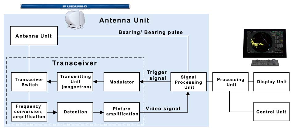
The whole radar system is mainly composed of the following devices.
- Antenna Unit (Antenna + Motor) : Antenna that radiates waves, Motor that rotates the Antenna
- Transceiver Unit: Unit generating waves and processing the signal
- Processing Unit: Unit processing signals from radar components and external devices
- Display Unit: Display of Radar screen and connected sensor data
- Control Unit: Radar controls
For our products, these components are combined into several units in an optimal way that takes into consideration installation needs.
Radar Basic commands
Here are in detail the different operations performed by each of the Radar components, from transmission to display of information.
- As soon as the trigger signal is sent by the "signal processing unit", the magnetron, then controlled by the voltage of the "Transceiver" modulator, emits a powerful microwave radiation. The microwaves are sent to the antenna via a special tube called "Waveguide" and are then re-emitted by the antenna in a specific direction.
- The emitted microwaves travel in a straight line over the water. These waves are reflected if they encounter an obstacle on their path and therefore inform of the presence of an object.
- The microwaves received by the antenna pass through several circuits: Frequency conversion, signal amplification, as well as video detection. Once the video is amplified, the signal is transformed in the antenna into a digital signal that will be sent to the processor.
- The signal sent to the processor, as well as the signals sent by all other devices connected to the processor, are transformed into visual data on a screen so that they can be easily interpreted by the user.
"To see", the mission of Radar.
A Radar antenna is a unit that transmits radio waves and receives the echoes of these radio waves. The performance of an antenna lies in its capability to detect the exact direction in which an object is located. It is therefore important to concentrate the rays in a particular direction if we want to know the exact direction of an object. This is called the directivity of radio waves.
The top part of an antenna is called the "slot antenna". The microwaves produced by the transmitter and receiver are emitted through a waveguide and transmitted from the slot inside the antenna. The "slot" is located on the front of the waveguide inside the antenna, tilting at each half wavelength interval. The angles of the slots are slightly different. By combining the radio waves emitted from each of the slots, it is possible to obtain a wave pointed at an extremely precise directional angle. The more slots there are, the more precise the direction angle. Thus, the longer the antenna, the more slots there are, increasing the directional angle precision.
About Microwaves
Since the microwaves used with Radars have an extremely short wavelength, they must be considered as waves going in a straight line like visible light. Microwaves are not refracted by the ionosphere like other waves below 30 MHz, so they can be considered as straight propagating waves over a visible distance.
Unlike visible light, microwaves are not absorbed by clouds or mist and remain generally unattenuated. These waves are therefore considered the ideal wavelength for navigation. The two main frequency bands used for navigation are the 3000MHz S-bands and the 9000MHz X-bands.
IEEE Classification of Microwave frequencies
Bandwidth (GHz) | Name | Application |
|---|---|---|
0.2~0.25 | G-band | Military air radio |
0.25~0.5 | P-band | Mobile communication |
0.5~1.5 | L-band | TV broadcast, mobile phone, Inmarsat satellite call |
2~4 | S-band | Fixed wireless, digital satellite broadcasting, ISM band (microwave, wireless LAN, amateur wireless etc) |
4~8 | C-band | Communication satellite, fixed wireless, wireless access |
8~12 | X-band | Military communications, meteorological satellites, earth observation satellites |
12~18 | Ku-band | Satellite TV broadcast, communication satellite |
18~26 | K-band | Communication satellite |
26~40 | Ka-band | Communication satellite |
40~75 | V-band | Radars, Communication satellite |
75~111 | W-band | Radio astronomy |
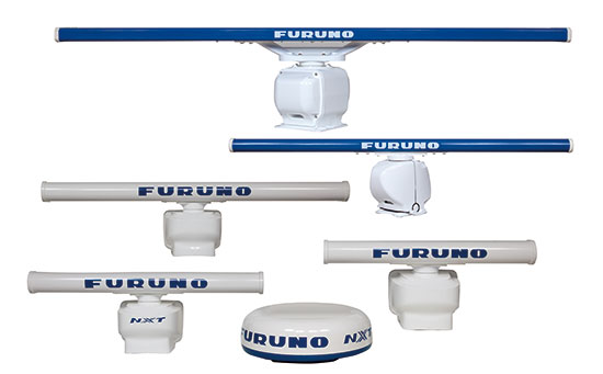
Several Radar antennas
The wavelength of X-bands is short, but the shorter the wavelength, the more straight the radio wave propagates and the easier it is to send directional waves and receive the reflected wave from the target.
The shorter the wave, the more precise and therefore efficient the antenna. Since all components of an X-band radar can be extremely compact, they have the advantage of being both economical, ergonomic and lightweight.
In the case of S-band Radars, they have a longer wavelength and undergo less attenuation, making it possible to detect distant targets. Despite their low power and reflection characteristic, S waves are poorly reflected by water surface, which is advantageous in navigation. They are often used in conjunction with X-band radars.
Radar glossary
Azimuth Resolution
Suppose that two separate objects are in the same direction, at the same distance, from the boat from which you are looking. The resolution of a radar depends mainly on the horizontal beam width, so the narrower the beam width of an antenna, the higher the resolution of the radar. To increase the resolution of a Radar, we need to reduce the horizontal beam width, which can be accomplished with a larger antenna. There are X-band radars with antennas up to 3 meters wide, and in this case the angular beam width is 0.75 degrees, which is very important for accuracy. On the other hand, Radomes, with an antenna width of about 40cm, have an average horizontal beam width of 5.7°.
Horizontal Beam Width and Vertical Beam Width
The horizontal beam width and the vertical beam width are two characteristics of a Radar antenna. While the horizontal beam width partly depends on the width of the antenna, the vertical beam width is fixed. It is generally of 20/25 degrees in order to avoid the effects of pitching and rolling.
Distance Resolution
Let's establish that the minimum distance between two objects located in the same direction but at different distances from the reference boat is the distance from which they can be distinguished on a screen. The distance resolution depends greatly on the pulse width. When the pulse width is short, the detection power is low but the distance resolution is good. Conversely, when the pulse width is long, the detection power is greater but the distance resolution is reduced. Since the pulse width has a direct influence on the distance resolution as well as on the detection power, it is automatically adjusted according to the detection range. There are about 3 types of pulse widths for small radars and from 4 to 6 for larger ones.
Pulse width
Radio wave radars use pulse waves and not continuous waves to increase detection capabilities. A pulse is an instantaneous signal, but it has a certain duration. At short range, the duration is about 0.08 microseconds, at middle range, 0.6 microseconds and at long range 1.2 microseconds. For short range, and despite the low power, short pulses have a high resolution and detection capability. For longer ranges, and to increase power, the pulse duration is extended. However, for the case of River Radars, when a high resolution is expected, it is necessary to set the pulse to "short".
Pulse Repetition Frequency
The Pulse Repetition Frequency corresponds to the number of transmitted pulses in one second. The unit is in Hz or PPS.
VRM (Variable Range Marker)
VRM: The VRM (Variable Range Marker) measures the range to targets. To measure range, press the key to display the VRM. It appears as a dashed circle. Adjust the VRM so that it touches the inner edge of the target. The range to the target appears in a data box on the display. Some Radars may display two VRM’s; the length of the dash of the #2 VRM is longer than that of the #1 VRM.
EBL (Electronic Bearing Line)
EBL: The EBL (Electronic Bearing Line) measures bearing to targets in degrees. To measure bearing, press the key to display the EBL. It appears as a dashed line. Adjust the EBL so that it bisects the target. The bearing to target appears in a data box on the display. Some Radars can display two EBL’s; the length of the dash of the #2 EBL is longer than that of the #1 EBL.
TT (Target Tracking)
TT (Target Tracking) is a function that helps prevent collisions by automatically tracking targets. By analyzing in detail the movement of other vessels, and tracking the vessel for a certain period of time using radar signals, it is possible to calculate the direction in which these vessels are heading, as well as their speed. Target information is displayed by numerical values and vectors on the Radar screen. For the reading of vectors, they point in the direction of the target while the length of the vector indicates the speed of the target.
The TT function also performs CPA and TCPA calculations. CPA is the shortest distance between the target vessel and owned vessel in real time, while TCPA indicates the time to maximum proximity between these two vessels.
CPA can be calculated for any target that has been acquired, mainly for those at risk of collision. When the CPA is too low, the vessel will be considered and displayed as dangerous, showing that an avoidance maneuvre is required.