- GNSS Antennas・Accessories
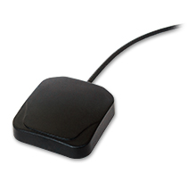
Multi-GNSS antenna
Model AU-18
Antenna for GPS signal (L1 band) and GLONASS (G1 band) reception
- GNSS (Timing, Automotive/Industrial)
Features
Suitable for use with GN-87, GV-87, and GT-87 receiver modules.
For timing applications and with high noise resistance, Multi-GNSS antenna AU-500/300 offer the best solution.
The antenna assembly consists of a patch antenna for receiving GNSS signals and a preamplifier for signal amplification.
Power supply to the antenna preamplifier must be provided by the application on the same RF signal trace as the GNSS RF signal is carried to the application.
Available with a choice of antenna connector type. The choice is SMA, BNC, GT-5 or SMB.
The antenna has an internal magnet so that it can be fixed on a metallic surface.
Easy to use antenna. Does not require RF or antenna knowledge.
Specifications
General
Input Frequency
1575MHz to 1610MHz
Polarization
R. H. C. P. (Right Hand Circular Polarization)
Antenna Gain
>= -0.5dBi (at 90° elev. angle)
>= -10dBi (at 10° elev. angle)
Output Impedance
50Ω
Total Gain
26±3dBi (1575.42MHz)
27±3dBi (1602MHz)
Pre. Amp Noise Figure
1.5dB (Typ) (3.0VDC, 1575.42MHz)
1.5dB (Typ) (3.0VDC, 1602MHz)
VSWR
<=2.0
Supply Voltage
1.8 to 5.5VDC
Current Consumption
10mA (Typ) (3.0VDC)
Operating Temperature
-40°C to +85°C
Storage Temperature
-40°C to +85°C
Operating Relative Humidity
40% to 95%RH
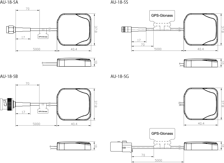
Series Lineup (Connector, Cable)
AU-18-5A (SMA(M), RG174 x 5m)
AU-18-5B (BNC(M), RG174 x 5m)
AU-18-5G (GT-5(F), RG174 x 5m)
AU-18-5S (SMB(F), RG174 x 5m)
Drawing
Inquiries about GNSS Products
- Specifications subject to change without notice.
GNSS Antennas・Accessories Product List
Multi-GNSS Timing Antennas
Model
AU-500/AU-300
Multi-GNSS antenna (For Timing)
Model
AU-217
GPS Antenna (For Timing)
Model
GPA-014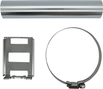
Antenna Mounting kit
Model
AFB-01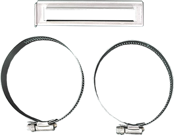
Antenna Fixing Bracket
Model
CP20-01111/CP20-00403/PM-001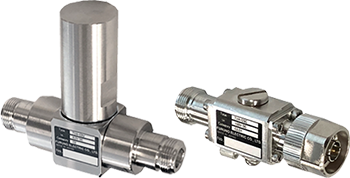
Coaxial lightning arrestor
Model
TVA-03C/TVA-03V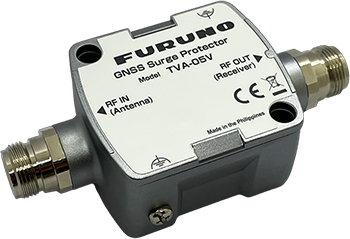
GNSS Surge Protector
Model
TVA-05V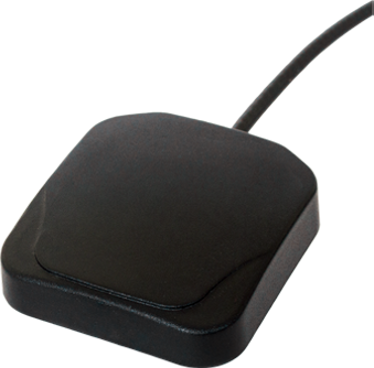
Multi-GNSS antenna
Model
AU-18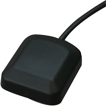
GPS Antenna
Model
AU-15There are no products that meet the conditions.
GNSS for Time Sync
Timing Multi-GNSS Receiver Module GT-100
Timing Multi-GNSS Receiver Module GT-90/GT-9001
Timing Multi-GNSS Receiver Module GT-88
Dual-Band GNSS Disciplined Oscillator GF-102/103/105S/105G
Multi-GNSS Disciplined Oscillatorv GF-8801/02/03
Multi-GNSS Disciplined Oscillator GF-8804/05
GPS Disciplined Oscillator GF-8048
Field Time Sync Generator TB-1
GNSS for Automotive & Industrial
GNSS Antennas・Accessories
Multi-GNSS Timing Antennas AU-500/AU-300
Multi-GNSS antenna (For Timing) AU-217
GPS Antenna (For Timing) GPA-014
Antenna Mounting kit AFB-01
Antenna Fixing Bracket CP20-01111/CP20-00403/PM-001
Coaxial lightning arrestor TVA-03C/TVA-03V
GNSS Surge Protector TVA-05V
Multi-GNSS antenna AU-18
GPS Antenna AU-15