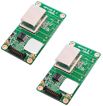
Timing Multi-GNSS Receiver Module
Model
GT-100Achieves the world's highest robustness and stability by receiving dual band(L1/L5)
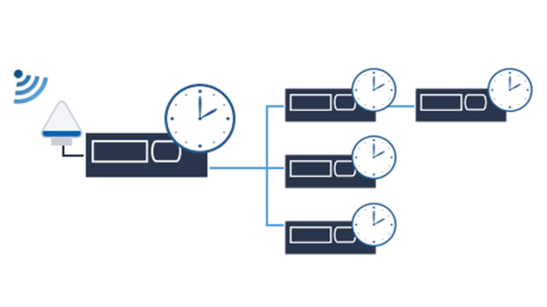
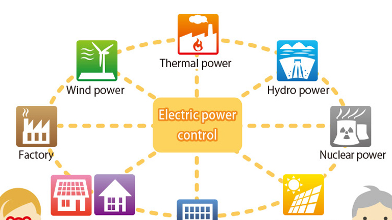
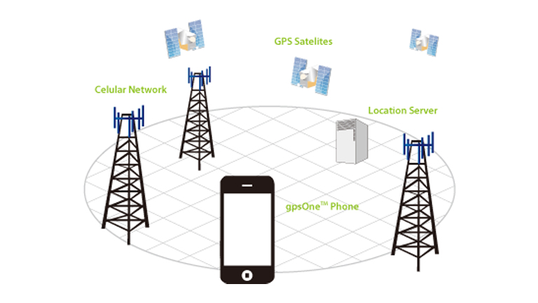
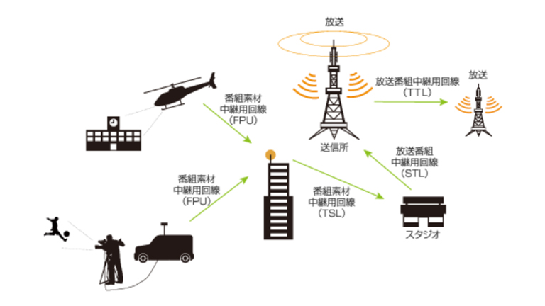
GPS/GNSS receivers can calculate not only the position but also the accurate time by receiving satellite signals. Accurate time information is used in infrastructure such as cell phone base stations, digital terrestrial broadcasting stations, and wireless systems that require time synchronization and accurate frequency.
This glossary mainly focuses on time and explains various associated terms. In addition, related general GPS/GNSS terms will also be explained. The content relates to Furuno's GNSS timing and frequency receivers GF/GT-88 series.
Please note that a"*" denotes a Furuno's original terminology.
White Paper: Countermeasure for GNSS receiver failure (Multipath, Jamming, Spoofing, Interruption of GNSS signal)
Telecommunication article: Basics of Network Time Synchronization
Telecommunication article: Supporting Industrial and Societal DX Through Time Synchronization
Global Positioning System (GPS), whose full name is NAVSTAR GPS, is the oldest GNSS and owned by the United States government and operated by the United States Space Force. GPS's standard positioning service started in 1993.
Global Navigation Satellite System (GLONASS) is a GNSS owned and operated by the Russian Federation. GLONASS has been available since 2011. GLONASS is also known as "URAGAN" which means storm in Russian.
Galileo is a GNSS owned by the European Union and operated by the European GNSS Agency (GSA). Galileo has been available since 2016.
BeiDou Navigation Satellite System (BDS) is a GNSS owned and operated by the People's Republic of China. BDS was previously called ComPass. BeiDou has been available since 2018.
Navigation Indian Constellation (NavIC) is a RNSS owned and operated by the Government of India. NavIC was previously called Indian Regional Navigation Satellite System (IRNSS). NavIc covers a large area centered around the South of the Indian Subcontinent with 7 satellites as of 2020. NavIC has been available since 2019.
Quasi-Zenith Satellite System (QZSS) is a RNSS owned by the government of Japan and operated by QZSS Services Inc (QSS). QZSS, also known as MICHIBIKI, covers Japan, East Asia and Oceania, with 4 satellites on a elliptical geosynchronous orbit, maximizing their availability at high elevation over Japan. QZSS has been available since 2018.
Satellite-Based Augmentation System (SBAS) is a regional geostationary satellite system that broadcasts, on the same L1 frequency as GPS, GNSS augmentation messages to improve the precision of the position and time of GNSS receivers. These augmentation messages provide integrity functions, differential correction information, and ranging functions. The differential correction information can be used for positioning to improve the position accuracy. Geostationary satellite systems like MSAS (Japan), WAAS (USA), EGNOS (EU), GAGAN (India) and some others are SBAS.
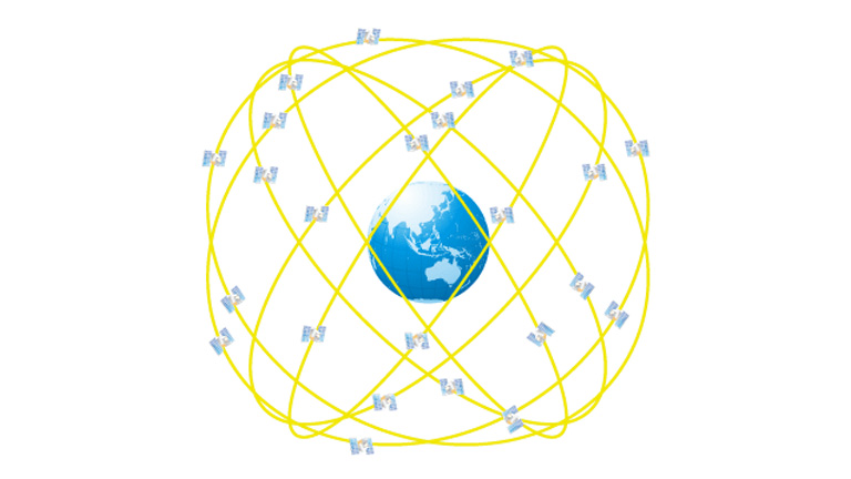
Global Navigation Satellite System (GNSS) is a general term describing any satellite constellation that provides Positioning, Navigation and Timing (PNT) information data on a global basis. GPS, Galileo, GLONASS and BDS/BeiDou are Global Navigation Satellite Systems.
Navigation Satellite System covering a more limited area, such as QZSS and NavIc, are classified as Regional Satellite Navigation Systems (RNSS).
A constellation is a group of stars. But in the GNSS industry, each satellite system managed by a different country or coalition of countries is referred to as a satellite constellation, like GPS of USA, GLONASS of Russia, Galileo of Europe Union and BeiDou of China.
ICD stands for Interface Control Document. ICDs are formal documents that specify the interface between the signals of a satellite constellation and the receiver. The ICDS of a GNSS are published by the relevant department of the country that operates this satellite constellation. Each satellite constellation has its own ICDs, and GNSS receivers are generally designed with reference to these documents. An ICD is not a permanent specification definition, but may be revised to correct errors or to enhance functionality. There is a possibility that some of the broadcast contents may be changed accordingly.
SVN stands for Space Vehicle Number. It is the serial number given to each navigation satellite and each satellite constellation is assigned a non-overlapping numbers. For example, for the GPS satellites, as of November 2020, SVN from 1 to 77 have been issued. Some of these SVNs are operational and others are decommissioned due to the satellite having reached its lifespan. SVN are used by the entities managing the satellite constellations, while users of GNSS receivers use PRN numbers to identify navigation satellites.
PRN stands for Pseudo random noise and refers to the PRN sequence or gold code, a unique and periodical pattern broadcasted by each operational navigation satellite. Each PRN sequence of a satellite constellation is referred to by a serial number, also called PRN number. For example, the GPS L1C/A signal uses 32 PRN sequences to uniquely identify each of its 32 operational satellites, which are referred to as PRN1 to PRN32. GNSS receivers receive these PRN codes, as the key of each satellite, to determine from which satellite the message came.
Since the PRN numbers are defined by satellite constellations, it is common for the GPS satellite PRN1 and the Galileo satellite PRN1 to be present at the same time. However, users of GNSS receivers sometimes have to determine to which constellation the PRN1 belongs to. This identification can be easily done by checking either the GNSS system ID in the GSA sentences or the talker ID of GSV sentences.
An ephemeris is one of the information that each GNSS satellite broadcasts.
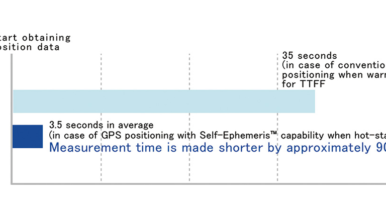
It shows the time and the detailed orbital information of the broadcasting satellite. This information is necessary for positioning, and it is repeatedly broadcasted in short cycles. GPS satellites broadcast their ephemeris for the L1C/A signal in 30-second cycles and usually valid for the next 4 hours.
Starting with valid ephemeris backup in the receiver is called HOT START.
An almanac is one of the information that GNSS satellites broadcast.
An almanac contains various correction information, UTC parameters, and rough orbital information for all the satellites of a constellation.
In the case of GPS satellites, the almanac is broadcast in 750 second cycles. Therefore, it may take up to 750 seconds from GPS time synchronization to UTC synchronization after initial positioning.
Starting with the almanac backup in the receiver is called WARM START. If neither the ephemeris nor the almanac are backed up in the receiver, this is called COLD START.
Each country's SBAS broadcasts a signal to reinforce GPS on the same L1 frequency as GPS. These reinforcement signals provide integrity functions, differential correction information, and ranging functions. The differential correction information can be used for positioning to improve the positioning precision.
SLAS Stands for sub-meter level augmentation service. This is a correction information broadcasted by QZSS satellites on L1S signal. It includes correction information that can be used to reduce ionospheric delays and errors from orbits, clocks, and other sources. As of 2020, its availability is limited to Japan and its surrounding seas.
A GNSS antenna receives the signals of GNSS satellites to provide a GNSS receiver with signal information to be decoded. Some GNSS antennas are small enough to be built into smartphones, while others are made to be resistant to harsh environments and purposed for a long-term outdoor installation. When selecting a GNSS antenna, one should keep in mind that the antenna should be designed to receive the frequency band(s) of the targeted satellite constellation(s), because the frequency band of the broadcasted signals may be different for each satellite constellation.
Open-Sky refers to an environment unobstructed with buildings, trees or any other structures all around the GNSS antenna. It is a commonly used term in the GNSS industry. In an open-sky environment, it is known that the precision of GNSS receiver's position and time is better because there is no obstruction or reflection of GNSS satellite signals. For this reason, the specifications of all GNSS manufacturers generally recommend placing the GNSS antenna in an open-sky environment.
In the GNSS industry, the term "indoor" is the counterpart expression to Open-Sky. It is not restricted to indoors but rather describes all environments where the received GNSS signals suffer attenuations or degradations or both. Heavily shielded urban areas or places under elevated structures or roads may be treated as indoor environments in the GNSS receiver specifications.
It should be noted that in completely shielded rooms it may be impossible to receive GNSS signals.
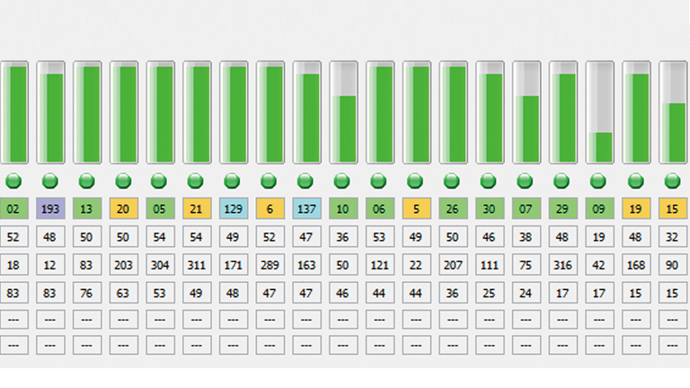
GNSS receivers output a value representing the strength of the signals received from the satellites. The received signal strength can be expressed in two ways. One is called Signal to Noise Ratio (SNR) and the other is called Carrier to Noise Density Ratio (C/N0). Both indicate the signal strength against the noise. C/N0, expressed in dB-Hz, is used in NMEA outputs to report the strength of the received GNSS signals.
dBm is a unit of measurement used to describe the strength of a signal in radio waves and in optics, and is commonly used in the GNSS industry. It represents a decibel milliwatt and is therefore calculated with a logarithmic function. This means that the strength of the signal is reduced by 1/2 for every reductions of 3 decibels.
As the signal becomes stronger, the dBm value increases, but as the signal becomes infinitely weaker, this value becomes negative. In fact, GNSS satellite signals are so faint that they are typically around -130 dBm in an open sky environment.
GNSS receivers output the strength of the signals received from each satellite in sentences called GSV. It is expressed as a Carrier to Noise Density Ratio (C/N0) and the unit is the dB-Hz. A dB (decibel) is a relative value, which is a different unit from the dBm. It is often used to express the strength difference between two signals, for example: "50dBm - 20dBm = 30dB".
For GNSS receivers, the thermal noise in a 1 Hz band at room temperature, -174 dBm, is generally used the noise reference and the C/N0 is calculated as the difference with the thermal noise. In other words, if C/N0 is 40dB-Hz, the GNSS received signal strength in 1Hz band is -134dBm. (-174dBm + 40dB = -134dBm)
Thermal noise is the electrical noise produced by heat. This is one of the factors that inhibit the transmission and reception of signals. If a signal is transmitted with a strength lower than the thermal noise, it will be buried in the noise and the other party will not be able to demodulate it correctly. For this reason, the thermal noise of -174dBm/Hz at room temperature is considered to be the limit of reception for GNSS receivers, and is used as the reference when calculating the Carrier to Noise Density Ratio (C/N0).
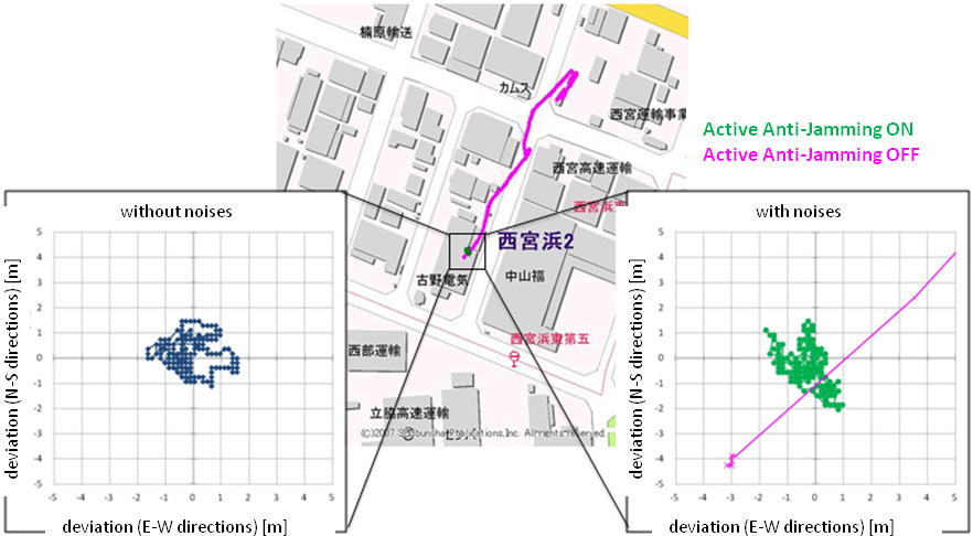
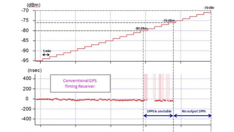
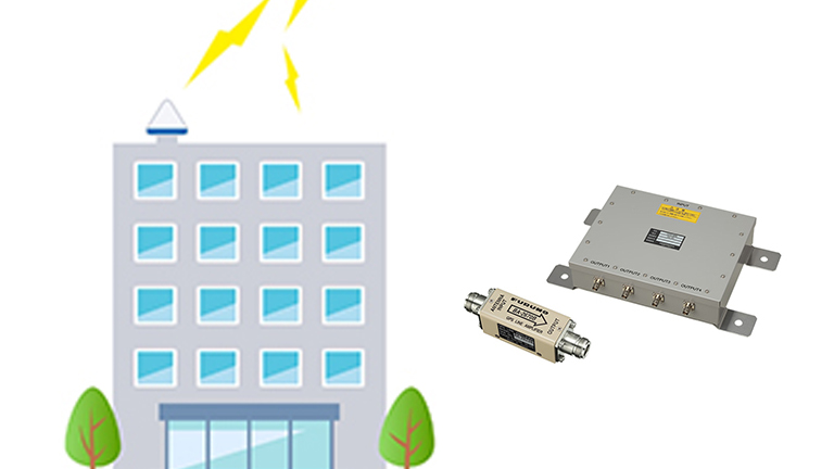
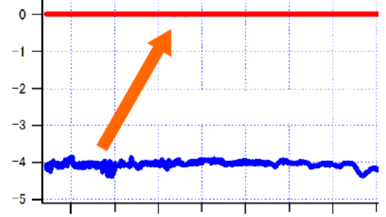
Jamming signals are electrical noises generated in or around the GNSS signal bands by other equipment or radios. Jamming signals are often intentionally broadcasted by malicious actors with the intend to affect the performance of near-by GNSS receivers.
Jamming signals will interfere with the reception of genuine GNSS satellite signals, which may result in poor or failed positioning.
Anti-jamming is the function that helps a GNSS receiver to sustain normal operation by detecting and removing interference waves so that GNSS satellite signals can be received as usual. However, since it is extremely difficult to detect and remove all interference waves, it is important to properly understand what the anti-jamming can do and cannot do.
Spoofing signals are signals generated by malicious actors that mimic genuine GNSS satellite signals and carry specially crafted information with the purpose to steer GNSS receivers to calculate wrong position, velocity and time information. Receiving such signals may affect the position and time.
Anti-spoofing is a feature integrated in the GNSS receivers to detect spoofing signals and to eliminate or reduce their influence, so that the true position, velocity and time can be calculated. However depending on the sophistication of the spoofing signals, it may be extremely difficult to detect and eliminate all spoofing signals. It is important to properly understand what the anti-spoofing can and cannot do.
A leap second refers to the occasional insertion of a one second to the Coordinated Universal Time (UTC) in order to maintain its synchronization with the earth rotation.
In general, a decision on a leap second insertion, which can be the addition or the subtraction of one second, is made at least one to two months prior its implementation. A leap second insertion is usually scheduled at the end of a quarter, but preferably on January 1st or July 1st.
Leap second insertions have taken place since 1972. Yet considering that the GPS and the QZSS satellites are operating with a starting date of January 6, 1980, our GNSS receivers are designed to output the cumulative value of leap seconds starting from January 6, 1980.
As of August 2020, the cumulative value of leap seconds since January 6, 1980 is +18 seconds. Unless the concept of leap second insertion is abandoned in the future, other leap second insertion events may happen from time to time.
Time Of Week (TOW), expressed in seconds, is the cumulative number of seconds in a week starting on Sunday at 00:00:00. It ranges from 0 to 604799, which corresponds to the following Saturday at 23:59:59. Therefore TOW rollovers to 0 each week on Sunday at 00:00:00. Each GNSS satellite broadcasts the current time using this concept of the TOW expressed in seconds and the week number.
In general terms, the week number is used to indicate the number of a week in a calendar year, starting from the beginning of January. However, in the GNSS industry, for example, in the case of GPS, Sunday January 6, 1980 was used as the starting point for week 0. the GPS week number continues to accumulate from 0 to 1023, without resetting its count at the end of year. The GPS week number that follows week 1023 is again week 0. This event is called a week number rollover.
UTC stands for Coordinated Universal Time and is the primary time standard in the world. It includes leap seconds and is the reference of the time we use on daily basis, that is without taking into account any time zone and daylight saving adjustments.
The UTC time is determined based on a network of atomic clocks located in many different countries all around the world. The time difference between all these reference atomic clocks is on the nanosecond scale. For example, in the case of the United States, the UTC time is set by the United States Naval Observatory and is called the UTC(USNO). Similarly, in the case of Russia, it is called UTC(SU).
GPS Time is the time system of GPS and is also the time system adopted by QZSS. It is broadcasted by the GPS and the QZSS satellites. It is a continuous time system that started on January 6, 1980 at midnight UTC. It does not take into account any leap second.
The GPS Time is broadcasted following the concept of the Time Of Week (TOW) expressed in seconds and the week number. The GPS week ranges from 0 to 1024, effectively rolling over approximatively every 19.8 years. After receiving both information GNSS receivers can compute the current GPS time, modulo the GPS week epoch. The GPS satellites broadcast UTC parameters, allowing GNSS receivers to also compute the current UTC(USNO) time, including the leap seconds.
In the last many years, the GPS Time is kept aligned to the UTC(USNO) time (modulo the leap seconds) within a few nanoseconds. There is no guarantee that this amount of error will be maintained in the future.
GLONASS Time is the time system of GLONASS and is broadcasted by the GLONASS satellites. It is a continuous time system that started on January 1, 1996. It is synchronized with UTC(SU) minus 3 hours and includes leap seconds.
GLONASS Time is broadcasted in a format allowing GNSS receivers to uniquely compute the current date and time util year 2100, without having to account for any week number rollover, unlike with the GPS Time. Since the GLONASS Time includes leap seconds, the correct alignment to UTC(SU) including the leap seconds is obtained by GNSS receivers as soon as the GLONASS time is decoded without having to wait for the reception of the UTC parameters.
The GLONASS satellites also broadcast the time difference between the GLONASS Time and the GPS Time, simplifying the time alignment between two systems for the GNSS receivers.
Galileo Time is the time system of Galileo and is broadcasted by the Galileo satellites. It is a continuous time system that does not take into account any leap seconds and that started on August 22, 1999 at 00:00:00, 13s ahead of UTC time. Galileo Time, GPS Time and QZSS Time are consistent with one another.
Galileo Time is broadcasted in a format allowing GNSS receivers to uniquely compute the current date and time without having to account for any rollover until February 19, 2078. Like for the GLONASS Time, this is a significant advantage compare to the GPS and QZSS Time.
The Galileo satellites broadcast UTC parameters, allowing GNSS receivers to compute the current UTC(EU) time. They also broadcast the time difference between the Galileo Time and the GPS Time, simplifying the time alignment between two systems for the GNSS receivers.
UTC parameters are information broadcasted by each GNSS satellite to allow converting a GNSS time system into UTC time. UTC parameters mainly include the leap second difference between a GNSS time and UTC time and the leap second insertion timing (except for GLONASS satellites as the GLONASS time already includes the leap seconds), as well as the nanosecond scale correction information.
The UTC parameters are included in a group of navigation messages, commonly referred to as an almanac, broadcasted at a regular time interval.
Several GNSS express their time system using the aforementioned concept of time of week and week number. The data size to transmit the week number differ for different systems and signals. For example, the GPS and QZSS L1C/A signals use a 10bit data size to transmit the week number; providing a week number from 0 to 1023. The week number that follow week 1023 is again week 0. This event is called week number rollover.
After a week number rollover occurs, GNSS receivers without special measures may output a date 1024 weeks out of date. Our GPS/GNSS receivers have been designed to deal with a GPS/ QZSS week number rollover and will continue to display the correct date after such an event. However, the range of date that can be properly converted is still up to 1024 weeks.
Depending on the product, this date, until which the correct date can be computed independently, is different. Please refer to the product specifications for details. Once this limited period of time has past, upon a restart without backup, the GPS/ GNSS receivers may display a date 1024 weeks or multiple of 1024 weeks out of date. In this case it is possible to set the correct date by sending a command to the GNSS receivers or by enabling the use of GLONASS and/ or Galileo satellites if supported. In the case of a continuous operation, our GPS/ GNSS receivers correctly maintain the current date and time upon week number rollovers.
The default leap second is a value that is applied to tentatively allow GNSS receivers to output the correct UTC time before the leap second information is obtained from the received UTC parameters. It is also possible to set the correct leap seconds upon start by sending a command to the GNSS receiver. GNSS receivers making use of the backup function are also be able to apply the correct leap second upon start. This setting is only used to display the correct UTC time before obtaining the correct leap seconds from the GNSS signals, so even if the default leap second is incorrect, it will not affect the reception of the satellite signals nor the positioning.
LZT stands for Local Zone Time. It provides the time offset value between UTC time and the local time
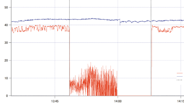
This is the numerical value of the variability (high reproducibility) of the time information outputs (1PPS and clock) of GNSS receivers.
For example, the standard deviation of the 1PPS output of a GNSS receiver indicates the stability performance of this receiver.
This is the numerical value of the accuracy of the time information output (1PPS) of GNSS receivers. That is the difference from the true value.
The definition of stability and accuracy are somewhat similar but are actually quite different when monitoring time. The terms accuracy and precision also appear in JIS standards. According to the JIS standard, precision is a measure of how little variation there is between multiple trials. Accuracy is a measure of how close the value is to the "trueness". For example, if a clock is off by a significant amount from the correct time, then it is described as "less accurate". If the watch is able to maintain that amount of deviation in the same way for months on end, then it can be described as "high precision". If the accuracy is low, it will not be practical, and if the precision is low, it will not be suitable for short-term time observation. Therefore, we believe that both stability and accuracy are important and should be specified separately.
PPS stands for Pulse Per Second. The GNSS receiver output providing a one pulse per second signal is called 1PPS.
1PPS is equivalent to 1 Hz clock. GNSS receivers for timing applications provide highly accurate time information to the outside world by accurately synchronizing the edge of this 1 PPS with UTC time or GPS Time (or any other supported GNSS Times). A pulse output with 2 pulses per second is sometimes referred to as 2PPS, and conversely, a pulse output with 1 pulse every 2 seconds is sometimes referred to as PP2S.
UTC synchronization is the state in which the time, the PPS and the VCLK frequency are all synchronized with UTC time. For this synchronization to be complete, GNSS receivers must receive the GNSS satellite signals, including the UTC parameters and calculate the time.
GPS synchronization is the state in which the time, the PPS and the VCLK frequency are all synchronized with GPS time. GNSS receivers will transition into GPS synchronization when either expressly set in this state or when the UTC parameters are not received.
RTC stands for Real Time Clock. In some of our timing products, the expression "RTC time synchronization" is used to explicitly indicate that the PPS and/or the frequency are in an uncontrolled state, either before the satellite signals are received and the time is fixed, or when the reception of the satellite signals is temporarily interrupted.
GNSS synchronization is the mode in which GNSS satellite signals are used to determine the receiver's time. This is the counterpart to the EPPS synchronization mode described below. Most GNSS receivers operate in this mode. When operating in GNSS synchronization mode, the receiver's operation state will be further classified into a finer state, such as GPS time synchronization or UTC time synchronization.
EPPS synchronization is the mode in which an external 1PPS inputted on the receiver EPPS pin is used as the time source instead of GNSS satellite signals. This is the counterpart to the GNSS synchronization mode. Some of our timing products support this mode.
Cable delay refers to the time it takes for a signal to travel through a cable. It depends on the cable type and length. In our products, the cable delay can be compensated by sending a command. The cable connected between the GNSS antenna and the GNSS receiver (and if applicable , the cable connected between the 1PPS output of GNSS receiver and the equipment) should be considered.
The GCLK frequency is an arbitrary frequency, that is generated by some of our timing products, using the GNSS receiver system clock and a built-in accumulator. When receiving GNSS satellite signals, these timing products can generate any frequency with a high accuracy.
As the arbitrary frequency is generated using an accumulator, it is important to consider whether the jitter and spurious contained in the GCLK frequency are acceptable for the intended application.
The VCLK frequency is the frequency output by the onboard voltage-controlled oscillator included in some of our timing products.
While receiving GNSS satellite signals, this frequency is adjusted based on the time acquired from GNSS satellites to provide a stable clock. Some our products can even continue to guarantee for a period of time the accuracy the VCLK frequency, when the reception of the GNSS satellite signals is interrupted (Holdover function).
The VCLK PPS is a PPS generated by dividing the VCLK frequency and whose edge is synchronized with the edge of PPS generated by the GNSS receiver. The VCLK PPS is available on some of our timing product.
Holdover is a function that tries to maintain as much as possible the high accuracy and high stability of the 1PPS and of the VCLK frequency, when the GNSS satellite signals can no longer be received. Some of our timing products support this function.
The learning period is a predetermined period of time during which the GNSS receiver, while continuously receiving GNSS satellite signals, learns the behavior of the onboard oscillator. This learning process is done automatically by the GNSS receiver, without any special awareness of the user. Once the learning period is completed, the holdover function is available.
The frequency control mode, available in our timing products with a VCLK frequency output, mainly indicates the stability level of the VCLK frequency. There are 6 different modes:
WARMUP : A state in which the receiver is waiting for the oscillator to have reached stability immediately after power-on.
PULL-IN : GNSS satellite signals are received and the VCLK frequency and PPS are being synchronized to the synchronization target based on the time obtained from the GNSS satellite signals.
COARSE LOCK : GNSS satellite signals are received and the VCLK frequency and PPS are synchronized to the synchronization target based on the time obtained from GNSS satellite signals. However, the synchronization precision is still coarse.
FINELOCK : GNSS satellite signals are received and the VCLK frequency and PPS are precisely synchronized to the synchronization target based on the time obtained from GNSS satellite signals.
HOLDOVER : When the GNSS satellite signals can no longer be received, it transitions into this mode if the learning period has been completed in advance. It automatically provides optimal control of the oscillator, taking into account its frequency aging characteristics and frequency-temperature characteristics, to maintain the accuracy and stability of the VCLK frequency and PPS at a much higher level than in free-running condition.
OUT OF HOLDOVER : It transitions into this mode after the holdover period has reached its maximum or when the GNSS satellite signals can no longer be received while the learning is not yet completed.
PVT calculation stands for position, velocity and time calculation. It refers to the calculation by a GNSS receiver of various information such as the receiver 3D position (latitude, longitude and altitude), speed, time and azimuth, based on the information received from the GNSS satellites. The PVT calculation is generally done using a Kalman filter. As it is an extremely important element for enhancing the receiver's performance, GNSS manufacturers are constantly working to further improve these algorithms. The accuracy of the position and time calculated by the GNSS receiver depends largely on its installation environment (strictly speaking, the antennas connected to the receivers). The number of received GNSS satellites with a high signal strength (using it in an open area) and whether these GNSS satellites are scattered in all directions (no obstruction or no bias in the direction of the satellites that can be received) have a significant impact on the accuracy of the PVT calculation.
Pseudorange is one of the information used by GNSS receivers for PVT calculation. It is the result of calculating the distance between a satellite and a GNSS receiver.
The Doppler frequency is one of the information that GNSS receivers use for PVT calculation. As the satellites and/or the receiver move, the frequencies of the signals received by the receiver are observed to be different from the frequency actually transmitted by the satellites (Doppler effect). This change is called the Doppler frequency.
RAIM stands for Receiver Autonomous Integrity Monitoring. It is a mechanism to identify and eliminate GNSS satellites that may adversely affect the PVT calculation. It is based on the principle of combination and majority rule and can be used when the number of received GNSS satellites is greater than the minimum number required for the PVT calculation. In timing products, T-RAIM, short for Time-RAIM, is sometimes used.
Fixed position is the term used in GNSS timing receiver applications to refers to the coordinates of the static position where the GNSS antenna is installed. It is expressed in terms of latitude, longitude and altitude. When the antenna installation location is unknown, the fixed position can be calculated and set automatically by the GNSS receiver using the SS mode.
Estimated position is the term used in GNSS timing receiver applications to refers to the process of calculating the fixed position in SS mode, while the position accuracy has not yet fully converged. In addition, the process of calculating the estimated position is called position estimation process.
General GNSS receivers must receive four or more GNSS satellite signals for the PVT calculation, thus to calculate information such as latitude, longitude, altitude, speed, azimuth and time.
Yet, if a GNSS timing receiver operates at a known static position and the latitude, longitude and altitude of this position are provided to the GNSS receiver, it can calculate accurate time and output PPS and VCLK frequency precisely synchronized with UTC time or a GNSS time, while receiving only one GNSS satellite signal.
For this reason, our GNSS receivers dedicated to time sensitive applications can operate in four different modes: NAV mode, which assumes the GNSS receiver does not operate at a static position and calculates the latitude, longitude, altitude, speed, azimuth, and time; TO mode, which assumes the GNSS receiver operates at a static position and precisely knows its position, and calculates only the time; SS mode which assumes the GNSS receiver operates at a static position and precisely estimate this position while calculating the time.
NAV mode : NAV mode stands for Navigation Mode. In this mode the GNSS receiver calculates the latitude, longitude, altitude, speed, azimuth, and time every second. The time precision of this mode is inferior to TO mode, but it must be used for non-static applications, in in-vehicle applications. In this mode, at least four or more satellites, except SBAS satellites, must be received.
TO mode : TO mode stands for Time Only mode. In this mode the GNSS receiver must operate in static position, must already know its precise position, and only calculates the time every second. It is possible to set the receiver in TO mode, by sending a command to the receiver with its precise position coordinates.
In TO mode, a GNSS receiver outputs a more accurate and stable PPS and VCLK frequency. In this mode a GNSS receiver can continue to calculate the time even when it receives only one GNSS satellite signal.
SS mode : SS mode stands for Self-Survey mode. SS mode is the mode for position estimation processing, which calculates the latitude, longitude, altitude of the static antenna installation location and time every second.
The SS mode is suitable for applications where the use of TO mode is desired but the exact static position of the GNSS receiver is unknown and must be first determined. Once the GNSS receiver has calculated its static position for a long enough period of time (24 hours by default) and/ or with a certain accuracy (configurable), it automatically transitions into TO mode.
DOP stands for Dilution Of Precision. It means the precision degradation rate. The smaller the precision degradation rate, the higher the precision. This value depends on the number of the received GNSS satellites and their positional relationship. If the satellites are evenly distributed in the sky, the DOP value will be smaller and the positioning accuracy will be higher. On the other hand, if there are buildings, trees, or other obstructions in the surrounding area, and the direction of the satellites that can be received is uneven, the DOP value becomes larger and the accuracy of the calculated position becomes worse.
The DOP value was a very useful indicator for monitoring the accuracy when only GPS satellites that could be received. In recent years, however, the number of available GNSS satellites has increased so much that it has become difficult to obtain a large DOP value. Meanwhile, in harsh environments such as indoor environments, multipath satellite signals are sometimes included in the DOP calculation, giving small DOP value that does not necessarily equate to high accuracy. So the DOP value should not be given too much importance. There are other types of DOPs, such as PDOP (Position Dilution of Precision), HDOP (Horizontal Dilution of Precision), and VDOP (Vertical Dilution of Precision), but the basic concept is the same for all of them.
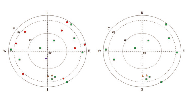
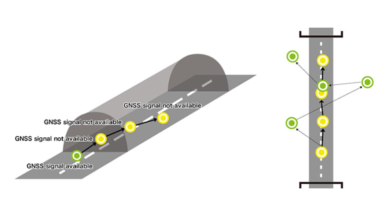
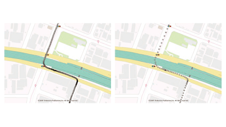
LOS stands for Line Of Sight. It refers to the direct reception of a GNSS satellite signal at the GNSS receiver's antenna, without any blocking obstacles or reflections. It is synonymous with an unobstructed view between a GNSS satellite and the GNSS receiver's antenna. Such GNSS satellites are specifically called LOS satellites. The more LOS satellites are received, the more stable the observed signal levels are, and the more accurate the PVT calculation is.
NLOS stands for Non Line Of Sight. A NLOS satellite is the opposite of a LOS satellite and indicates the presence of an obstruction between a GNSS satellite and the GNSS receiver's antenna. Strictly speaking, a GNSS satellite whose signal is not received at the GNSS receiver's antenna, is determined to be non-visible and is also included in NLOS satellites. However, in our case, we simply call such satellites as non-visible satellites and not as NLOS satellites.
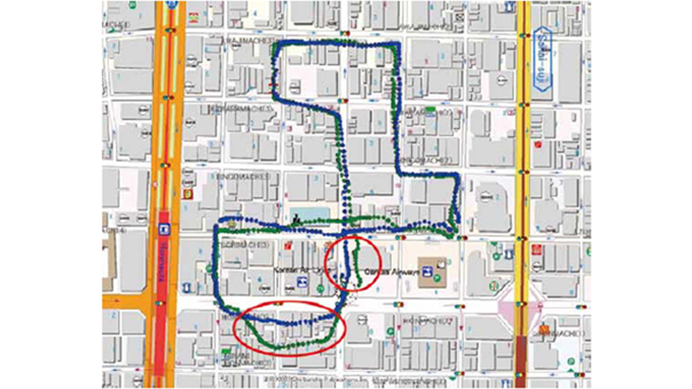
A NLOS satellite is defined as a GNSS satellite whose signal cannot be received directly at the GNSS receiver's antenna, but only a faint signal of it that is reflected by surrounding buildings or attenuated by an obstacle is received. A signal that is received from a reflection and/ or by travelling through an obstacle is referred to as multipath.
Using multipath GNSS satellite signals for the PVT calculation tends to result in poor position accuracy and time accuracy due to errors in the calculation of their pseudoranges and Doppler frequencies. Determining which GNSS satellites are NLOS satellites, masking them appropriately, and using only LOS satellites for the PVT calculation improves the position accuracy and time the accuracy.
A protocol is a communication procedure that uses a communication port to send and receive data.
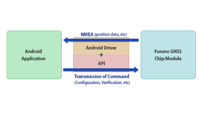
A command is a set of data sent to a GNSS receiver to configure or query it.
A Sentence is a set of data received from a GNSS receiver.
Serial data is a generic term referring to a set of data sent or received sequentially on a communication port.
The term "serial data output" is sometime use instead of "sentences".
NMEA is an abbreviation for a communication protocol prescribed by the National Marine Electronics Association.
ACK stands for Acknowledgement, which means an affirmative response. ACK is a unique signal to indicate that a command has been successfully received. When a command is sent to a GNSS receiver and is accepted as appropriate, ACK is returned as a response by the GNSS receiver.
NACK stands for Negative-Acknowledgement, which means a negative response. NACK is a unique signal to indicate that a command has been unsuccessfully received. When a command is sent to a GNSS receiver and is deemed as improper, NACK is returned as a response sentence by the GNSS receiver. If NACK is returned, it is often because the command is either not properly formatted or checksummed.
BBRAM stands for Battery Backup Random Access Memory. This storage area can be used as a backup area only when a backup voltage is applied to the GNSS receiver while it is turn-off. Ephemeris data, almanac data, and configuration values are sequentially stored in this area. This storage area is read out at the time of start-up or restart. The stored information can be deleted by removing the backup voltage or invalidated by sending specific commands to the GNSS receiver.
FLASH ROM (FLASH) refers to a storage area contained in a FLASH ROM.
By sending the FLASHBACKUP command to the receiver, it will save ephemeris data, almanac data, last position and configuration values to FLASH. This storage area is read out at the time of startup or restart.
Once baked up to FLASH, the settings can only be erased by either using the FLASHBACKUP command again or updating the GNSS receiver software. However these settings can be invalidated by sending specific commands to the GNSS receiver.
If a setting for the same item is stored in both BBRAM and FLASH, the BBRAM setting takes precedence. Yet, if the data in BBRAM are invalid for reasons such as a loss of backup voltage, the FLASH data will be applied at the next startup or restart.
We provide technical white papers for each of the typical failures caused by GNSS receiver. For each failures, our experts in time synchronization explain details about countermeasures on receiver side, using diagrams to show the effectiveness, and how to select products. If you are considering a GNSS receiver for the first time, please take a look.
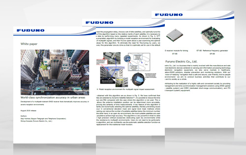
A special download of the feature article "Basics of Network Time Synchronization," which published in the December 2021 issue of Telecommunication, is available.
The magazine covered multiple companies, resulting in a comprehensive article that is not biased toward any one company.
You can view the PDF as it looks in the magazine.