Marine Radar
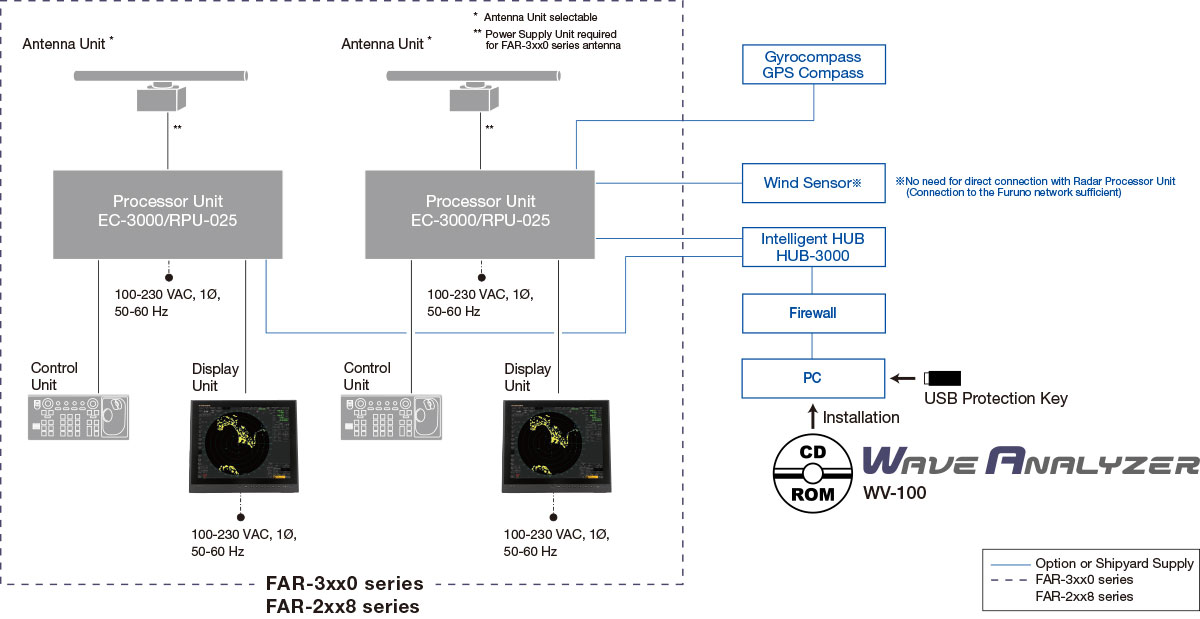
Wave Analyzer Model WV-100
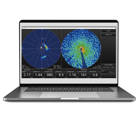
The power of digitized information to support visual observation
Merchant Marine
Workboats
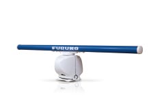
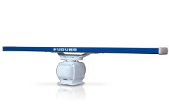
Marine Radar
* As the Wave Analyzer is a computer-based program, it does not affect the performance of the Radar system.
| PRODUCT NAME | Wave Analyzer | ||
|---|---|---|---|
| MEASURING RANGE | Wave height | 0.10 to 15.0 m | |
| Wave period | 4.00 to 16.00 s | ||
| Wave direction | 2 max. | ||
| Bearing | -140 to +140° (from the bow) | ||
| Distance | 150 to 1,200 m | ||
| SEA WEATHER CONDITIONS | Sea state code | 3 minimum (wave height: 0.5 m or above)* | |
| Beaufort scale | 3 minimum (wind speed: 3.4 m/s or above)* | ||
| Sea Depth | 0.5 times or more of the measured wavelength | ||
| MONITOR (USER SUPPLY) | Display resolution | SXGA/UXGA/FHD | |
| Language | English | ||
| INTERFACE | LAN | 2port -Ethernet 100Base-TX | |
| RS-232C | 1port (USB/RS-232C converter available) | ||
| Data sentence | LAN (Input) | MWV | |
| PFEC (Output) | RAwv1, RAwv2 | ||
| EQUIPMENT LIST | CD-ROM (Wave Analyzer and Operation Manual) USB Protection Key Installation Manual |
||
* Specifications subject to change without notice.